|
BA1404 stereo coder/FM transmitter |

OSC and RF coils data:
2.25 tuns of 0.5 mm enamel wire on 5 mm diameter ferrite core
|
The other IC stuff available:
BH1414F
BH1415F
BH1416F
|
|
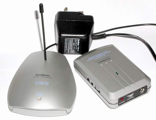
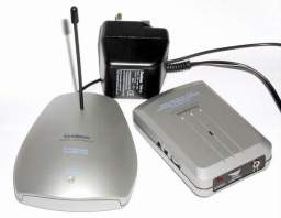
Goodmans GPR 9000 RF |
|
The cheap 900 MHz FM radio. Claimed to operate on 2 fixed frequencies around 86 MHz.
You can get yours from http://www.argos.co.uk for some 40 bucks.
Good value for money. The design is based on BA1404 ROHM chip. Contains AGC circuit based
on BA3308 amp and timer unit that controls RF module. Can be modified to transmit
in 100 MHz band.
|
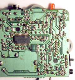
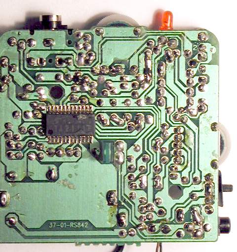
Receiver, copper side, click for full-size image
|
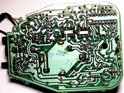
Receiver, parts side, click for full-size image
|
IC1 TDA2822M
IC2 TA2111F
|
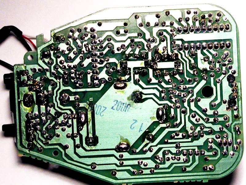
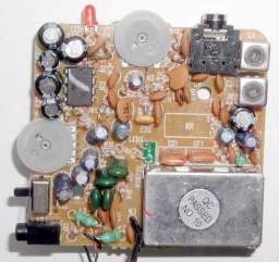
Transmitter, copper side,
click for full-size image
|
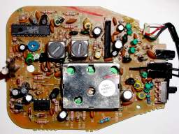
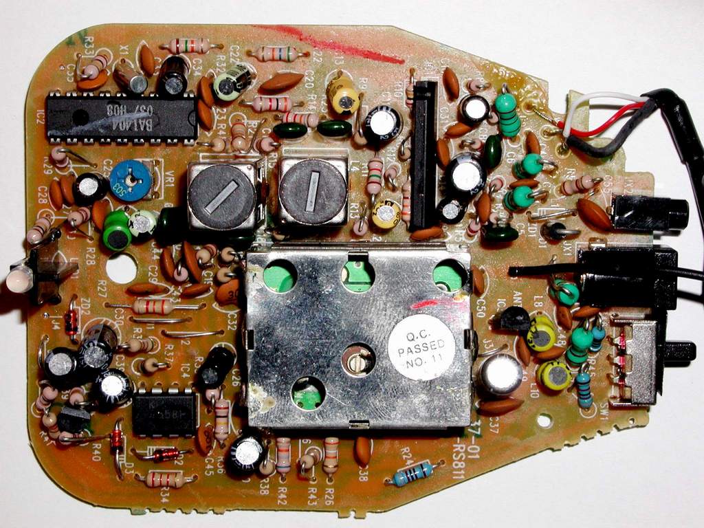
Transmitter, parts side,
click for full-size image
|
IC1 BA3308
IC2 BA1404
IC3 78L08
IC4 KIA4558P
|
|
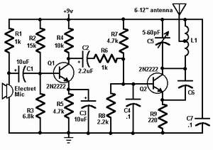
Simple FM transmitter |
|
This circuit is a simple two transistor (2N2222) FM transmitter.
No license is required for this transmitter according to FCC regulations regarding wireless microphones.
If powered by a 9 volt battery and used with an antenna no longer than 12 inches, the transmitter will be
within the FCC limits. The microphone is amplified by Q1. Q2, C5, and L1 form an oscillator that
operates in the 80 to 130 MHz range. The oscillator is voltage controlled, so it is modulated by the
audio signal that is applied to the base of Q2. R6 limits the input to the RF section, and it's value can
be adjusted as necessary to limit the volume of the input. L1 and C6 can be made with wire and a
pencil. The inductor (L1) is made by winding two pieces of 24 gauge insulated wire, laid side by side,
around a pencil six times. Remove the coil you have formed and unscrew the two coils apart from
each other. One of these coils (the better looking of the two) will be used in the tank circuit, and the
other can be used in the next one you build. The antenna (24 gauge wire) should be soldered to the
coil you made, about 2 turns up from the bottom, on the transistor side, and should be 8-12 inches
long. To make C6, take a 4 inch piece of 24 gauge insulated wire, bend it over double and,
beginning 1/2" from the open end, twist the wire as if you were forming a rope. When you have
about 1" of twisted wire, stop and cut the looped end off, leaving about 1/2" of twisted wire
(this forms the capacitor) and 1/2" of untwisted wire for leads.
Source: "Radio-Electronics" Magazine, Nov,91 issue (C) Copyright Gernsback Publications, Inc., 1991
|